
Power System Studies
Evaluate what a planned change means for your facility’s electrical distribution before committing to equipment, settings, or an outage. AES scopes the analyses around the decision you need to make and documents the conditions behind the results.
When to call
Start here when adding a major load, replacing distribution equipment, integrating a generator or transfer switch, or investigating recurring trips. A study can also help evaluate equipment duties or proposed protection settings before procurement or construction.
What to have ready
Share the facility city and state, the decision to be made, and your bid, installation, or outage date. Useful inputs include one-line diagrams, utility fault-current data, major loads, transformer and equipment ratings, and current protective device settings. Note which items are proposed or unverified. AES can arrange private transfer for detailed records.
What to prepare for an electrical studyWhat the study can deliver
- A report describing the model, study cases, inputs, and assumptions that affect the conclusions.
- Results matched to scope, such as fault-duty comparisons, time-current plots, or voltage and loading summaries.
- Prioritized findings and recommendations for equipment ratings, protective settings, or further field verification, as applicable.
Choose the analysis that answers your question
Short circuit
Evaluates available fault current and compares the calculated duty with equipment ratings in scope.
Protective device coordination
Compares device response and identifies where a downstream fault could also open an upstream device.
Load flow
Evaluates voltage and equipment loading for agreed conditions, such as existing and proposed loads or utility and standby service.
Selected work samples
Redacted examples of field documentation and engineering drawings.
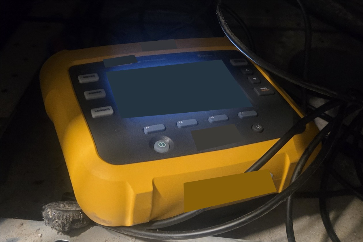
Field load monitoring
AES used a portable power meter to log how much power the existing system drew during a load-capacity evaluation.
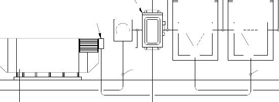
Standby-power one-line riser
An excerpt from a standby-power permit drawing shows how the generator, utility metering and transfer equipment fit together.
- Standby generator. Provides backup power.
- Utility meter. Measures electricity supplied by the utility.
- Fused disconnect switch. Isolates the circuit and provides fuse protection.
- Automatic transfer switch. Changes the power source automatically.
- Manual transfer switch. Lets an operator select the power source by hand.
Study basis
AES agrees the system boundary, cases, and governing requirements before analysis. Utility source assumptions, equipment data, and operating modes can change the results. Changes to field settings or equipment require a separate implementation decision and verification appropriate to the facility.
Tell us which equipment or loads are changing and what you need to decide.
Request a power system consultation